
Failure Analysis
Table of Contents
Failure Analysis and Anomaly Investigation for Electronic Components
A failed component rarely explains why it failed.
Electrical symptoms, intermittent behavior, visible damage, parametric drift, and field-return conditions are starting evidence, not root cause. Failure analysis combines controlled electrical, imaging, physical, and materials-analysis techniques to move from the observed symptom to the failure site, failure mechanism, and the most supportable cause.
AAA Engineering & Test Lab develops customer-defined failure analysis plans for electronic components, microcircuits, discrete semiconductors, passive devices, assemblies, and related hardware. The investigation is structured around the failure signature, device construction, available history, sample condition, and the engineering decision the customer must make.
Discuss a Failure or Anomaly
Failure Analysis Services Available from AAA
AAA Engineering & Test Lab performs customer-defined failure analysis and anomaly investigations for microcircuits, discrete semiconductor devices, passive components, packages, interconnects, and other confirmed electronic-component types. Investigations are planned to preserve evidence, confirm the failure signature, localize the condition, expose the failure site, and determine the most supportable mechanism and cause.
- Failure-history review and evidence-preservation planning
- Electrical confirmation, parametric testing, curve tracing, and continuity or resistance mapping
- External visual, radiographic, and acoustic-microscopy examination
- Targeted delidding, decapsulation, cross-sectioning, polishing, and material removal
- Optical microscopy, SEM imaging, EDS elemental analysis, and XRF evaluation
- Bond-strength, bond-pull, die-shear, solder, termination, and interconnect assessment
- Comparative analysis of failed, unfailed, same-lot, and known-good samples
- Evaluation of evidence consistent with ESD, EOS, moisture, corrosion, contamination, thermal, mechanical, package, and process-related mechanisms
- Root-cause assessment, alternative-hypothesis review, and corrective-action support
- Engineering reporting with imagery, measurements, limitations, and conclusion confidence
What Failure Analysis Determines
- Failure confirmation. Reproduce or verify the reported electrical, functional, mechanical, or visual anomaly where the sample condition allows it.
- Failure localization. Narrow the problem to a circuit node, die region, package interface, interconnect, termination, material system, or assembly feature.
- Failure mechanism. Identify the physical, electrical, chemical, thermal, mechanical, or radiation-related process associated with the observed failure.
- Root-cause assessment. Correlate laboratory evidence with design, process, handling, environmental, application, or supplier history.
- Population risk. Determine whether the evidence appears isolated, lot-related, process-related, design-related, or representative of a broader condition.
- Corrective-action support. Provide documented evidence for containment, redesign, screening, process correction, supplier action, or further testing.
How Failure Analysis Applies Across the Program Lifecycle
Development and Design Verification
Investigations can identify design margins, construction vulnerabilities, process interactions, or unexpected device behavior before production release.
Qualification and Reliability Testing
Failures generated during environmental, life, radiation, mechanical, or electrical stress can be analyzed to determine whether the mechanism is relevant to the intended application.
Production and Yield Escalation
Repeated test rejects, drift, intermittent behavior, or assembly defects can be examined to separate process escapes from device, fixture, handling, or test-system effects.
Supplier and Lot Investigation
Failure analysis can compare affected and unaffected samples, evaluate lot consistency, and produce evidence for supplier corrective action or source disposition.
Field Return and Mission Anomaly
Returned hardware can be evaluated under a controlled chain of evidence to identify the most supportable mechanism without destroying critical evidence too early.
Obsolescence and Alternate-Source Evaluation
Comparative analysis can reveal construction or performance differences that matter when replacing an unavailable device or introducing an alternate source.
When Programs Use Failure Analysis
- A component does not meet electrical or functional requirements.
- A device passes initial screening but fails after environmental, life, radiation, or assembly stress.
- Intermittent behavior cannot be explained by routine production testing.
- Radiography, acoustic microscopy, visual inspection, or DPA reveals an anomaly requiring mechanism-level investigation.
- A field return or system anomaly must be traced to the component, package, interconnect, board, or application environment.
- Repeated failures suggest a process, material, supplier, or lot-related condition.
- Objective evidence is needed before supplier escalation, corrective action, redesign, or containment.
- A suspected ESD, EOS, moisture, corrosion, contamination, bond, die-attach, metallization, package, or solder-interconnect failure requires confirmation.
How Risk and Evidence Drive the Investigation Plan
Failure analysis must preserve the evidence needed for later steps. The correct plan usually progresses from non-destructive confirmation and localization toward increasingly invasive analysis.
- Known history. Part number, lot, source, assembly history, stress history, failure signature, system conditions, and prior testing affect the hypothesis set.
- Sample condition. A powered failure, open circuit, short, intermittent device, cracked package, contaminated surface, and previously decapsulated sample require different handling.
- Reference population. Known-good, unfailed, same-lot, alternate-lot, and exemplar samples strengthen comparative interpretation.
- Evidence sequence. Cleaning, probing, acoustic immersion, solvent exposure, decapsulation, sectioning, and material removal can alter evidence.
- Decision threshold. The customer may need mechanism identification, probable root cause, definitive root cause, lot-risk assessment, or enough evidence to support containment.
- Destructive limits. Some samples must remain available for electrical comparison, supplier review, legal evidence, or follow-on testing.
Have Questions?
Submit the contact form below and one of our electrical testing experts will connect with you right away.
Governing Standards and Technical Frameworks
- MIL-STD-883. Provides microcircuit visual, mechanical, electrical, environmental, and physical-analysis methods that may support failure localization and mechanism analysis, including Method 5003, Failure Analysis Procedures for Microcircuits, which defines the post-failure examination sequence.
- MIL-STD-750. Provides methods for discrete semiconductor devices, including electrical characterization, visual inspection, radiography, bond evaluation, and life or environmental stresses.
- MIL-STD-202. Provides methods used for passive and electromechanical components.
- MIL-STD-1580. Provides a DPA framework that may generate or confirm physical evidence, but DPA and failure analysis begin with different engineering questions.
- JEDEC methods. Support semiconductor package, moisture, temperature, electrical, and reliability investigations.
- ASTM practices. Support radiography, materials examination, cross-sectioning, spectroscopy, and related analytical work where applicable.
- AS6171 methods. Apply when the primary question is suspect-counterfeit risk. Counterfeit testing and failure analysis may share techniques but do not share the same conclusion framework.
Key Failure Analysis Methods and Capabilities
AAA Engineering & Test Lab uses exact MIL-STD methods and analytical capabilities within customer-defined failure analysis investigations. Method selection is driven by the failure signature, device construction, evidence state, and governing requirement, not by credential status. Where an invoked method falls within AAA’s approved DLA suitability scope, that credential is stated at the exact-method level. Methods and analytical techniques outside the DLA credential set remain valid failure-analysis capabilities which AAA performs or supports the work.
MIL-STD-883 Failure Analysis Procedure
MIL-STD-883 Method 5003 – Failure Analysis Procedures for Microcircuits. Provides the procedural framework for post-failure examination of microcircuits and helps structure evidence preservation, examination sequence, localization, destructive escalation, and reporting. AAA can use Method 5003 where it is invoked by the governing failure-analysis requirement; no DLA suitability claim is made for Method 5003.
Electrical Confirmation and Localization
- Parametric and functional testing. Confirms the failure signature and identifies parameters, pins, states, temperatures, or operating conditions associated with the anomaly.
- Curve tracing and leakage analysis. Compares junction, protection, or terminal behavior against known-good or expected response.
- Resistance and continuity mapping. Helps isolate opens, shorts, intermittent connections, and abnormal current paths.
Non-Destructive Imaging
- Radiographic inspection. Evaluates die location, wire bonds, lead frames, voiding, internal alignment, foreign material, and package construction.
- Acoustic microscopy. Detects delamination, voids, cracks, porosity, and interface changes in plastic-encapsulated, multilayer, and other moisture-sensitive or interface-critical constructions.
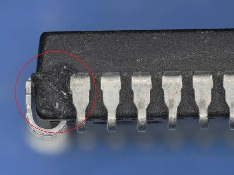
- External visual inspection. Documents package, lead, marking, surface, fracture, corrosion, contamination, and handling evidence before invasive work.
Physical Access and Cross-Section
- Decapsulation and delidding. Expose the die, bonds, cavity, substrate, or internal construction for targeted inspection.
- Cross-section analysis. Reveals package, plating, solder, via, termination, die-attach, bond, and material interfaces at a selected plane.
- Dye penetrant or complementary sectioning. May reveal cracks, separation, or interfacial paths where the approved procedure supports it.
Microscopy and Materials Analysis
- Optical microscopy. Documents surface and cross-section features across a broad magnification range.
- SEM and EDS. Provide high-resolution imaging and elemental analysis of fracture surfaces, residues, metallization, corrosion, and material differences.
- Supports elemental and finish evaluation without requiring immediate destructive sectioning.
- FTIR or Raman. May support polymer, coating, residue, ink, or contamination analysis where capability and sample condition permit.
Mechanical Integrity
- Bond pull and bond strength. Evaluate interconnect integrity and record the separation mode.
- MIL-STD-883 TM 2011 Bond Strength is an exact microcircuit route within AAA’s approved DLA suitability scope. MIL-STD-750 TM 2037 Bond Strength (Destructive Bond Pull Test) may be used for applicable discrete-device investigations without a DLA suitability claim.
- MIL-STD-883 TM 2019 Die Shear Strength provides an exact die-attach mechanical-integrity route within AAA’s approved DLA suitability scope.
- Die shear. Evaluates die-attach mechanical integrity and failure interface.
- Solder and termination evaluation. Examines cracks, intermetallics, wetting, voiding, plating, and mechanically induced damage.
How a Failure Analysis Investigation Is Structured
1. Define the Failure and Decision
Review the reported symptom, device history, stress history, system conditions, prior data, available samples, and the decision the customer must make.
2. Preserve and Document the Evidence
Record sample condition, packaging, markings, visible damage, contamination, prior handling, and chain of custody before cleaning or testing.
3. Confirm the Failure Signature
Use the least invasive electrical or functional approach that can confirm the reported behavior without masking or extending the failure.
4. Localize the Failure
Use electrical comparison, radiography, acoustic microscopy, optical inspection, and targeted measurements to narrow the area of interest.
5. Expose the Failure Site
Use controlled delidding, decapsulation, sectioning, polishing, or material removal selected for the package and suspected mechanism.
6. Characterize the Mechanism
Apply microscopy, mechanical testing, spectroscopy, elemental analysis, and comparative evidence to determine how the failure developed.
7. Correlate Cause and Contributing Factors
Compare laboratory evidence with design, process, assembly, application, environmental, supplier, and test history.
8. Report Findings and Confidence
Separate direct observations, measured data, interpretation, alternative explanations, limitations, and conclusion confidence.
Failure Analysis Deliverables
AAA’s failure-analysis deliverable package is expected to document the progression from the reported symptom to the observed failure site, mechanism, and most supportable cause. Final deliverables depend on sample condition, preserved evidence, approved methods, and the investigation objective.
- Sample identity, source, lot, date code, assembly level, and available operating history
- Documented failure signature and reproduction conditions
- Investigation plan, evidence sequence, destructive authorization, and deviations
- Electrical data, curves, plots, resistance or continuity results, and comparison data as applicable
- External, radiographic, acoustic, optical, cross-section, and SEM imagery
- EDS, XRF, or other materials-analysis results as applicable
- Failure localization and affected interface or feature
- Observed failure mechanism and evidence supporting the interpretation
- Alternative explanations, limitations, confidence level, and unresolved questions
- Root-cause assessment, population-risk considerations, and recommended corrective or containment actions
- Final engineering report and supporting raw data or image package as defined by the project
What Failure Analysis Results Can Show
- Whether the reported failure can be confirmed under defined conditions
- The physical or electrical location associated with the failure
- The observed failure mechanism and affected interfaces
- Evidence consistent with electrical overstress, ESD, corrosion, contamination, moisture, thermal fatigue, mechanical damage, interconnect failure, die-attach failure, package damage, or process variation
- Differences between failed, unfailed, same-lot, or reference samples
- Whether the evidence supports an isolated event or indicates possible population risk
- The data and images needed for corrective action, containment, redesign, additional screening, or further testing
What Failure Analysis Cannot Establish
- A root cause cannot always be proven from one failed sample. Critical evidence may be destroyed by the failure event, prior handling, field use, or earlier analysis.
- Correlation is not automatically causation. An observed anomaly may be a consequence of the failure rather than its initiating cause.
- Laboratory reproduction may not duplicate the field environment. System interactions, transient conditions, software states, mechanical loading, or application history may be unavailable.
- A passing reference sample does not prove the failed sample was unique. Population risk depends on sampling, lot history, and comparative evidence.
- Failure analysis does not replace qualification or screening. It explains a failure or anomaly; it does not establish full product suitability.
- Testing alone does not prove authentic provenance. Identity and traceability questions require the appropriate counterfeit-risk framework.
Common Failure Analysis Misapplications
Starting Destructive Work Before Confirming the Failure
Opening or sectioning the sample too early can destroy the electrical signature, contaminate surfaces, or remove the evidence needed to distinguish cause from consequence.
Calling Every Anomaly the Root Cause
A crack, residue, void, or damaged bond may be real but still secondary. The conclusion must explain how the evidence connects to the reported failure.
Using DPA and Failure Analysis as Synonyms
DPA is commonly proactive and lot-focused. Failure analysis begins with a known failure or anomaly and seeks mechanism and cause.
Relying on One Technique
Radiography, SEM, EDS, XRF, electrical testing, or acoustic microscopy can each reveal important evidence, but no single technique resolves every mechanism.
Ignoring the System and Application History
Device evidence must be correlated with bias, temperature, timing, assembly, handling, radiation, moisture, mechanical, and operating history.
When Failure Analysis Alone Is Not Sufficient
- Destructive Physical Analysis. Use when representative lot samples must be evaluated for construction, materials, workmanship, or lot quality.
- Qualification or Reliability Testing. Use when the question is whether the product can withstand defined environmental, electrical, radiation, life, or mechanical stresses.
- Counterfeit Detection. Use when source risk, traceability, remarking, material substitution, or identity inconsistency is the primary question.
- System-Level Investigation. Use when the component may have responded to board, software, power, grounding, thermal, mechanical, or electromagnetic conditions.
- Supplier Process Review. Use when root cause depends on wafer, assembly, plating, material, process-change, or production records held by the manufacturer.
- Statistical Population Analysis. Use when one or a few failed devices cannot support a broader lot or fleet conclusion.
Credentials Relevant to Failure Analysis
Failure analysis depends on controlled methods, traceable equipment, disciplined sample handling, and clear evidence reporting. AAA maintains quality, laboratory, ESD-control, security, and method-specific credentials applicable to its confirmed scope.
Where a failure investigation includes one or more of AAA’s confirmed DLA-suitable methods, the proposal and test plan should identify those methods explicitly. Current credentials and suitability information are available on the Accreditations & Certifications page and the DLA’s List of Commercial Laboratories Suitable for Testing Military Devices.
How to Evaluate a Failure Analysis Laboratory
- Evidence-first planning. The laboratory should define how the sequence preserves electrical, surface, internal, and material evidence.
- Breadth of complementary methods. Electrical, radiographic, acoustic, physical, mechanical, and materials-analysis capabilities reduce handoff gaps.
- Package and device experience. Preparation and interpretation must match the actual device construction.
- Reference-sample strategy. The laboratory should explain what known-good, same-lot, or comparison samples would improve the conclusion.
- Artifact control. Analysts must distinguish original damage from probing, cleaning, decapsulation, polishing, etching, or sectioning artifacts.
- Mechanism versus cause discipline. Reports should separate the observed failure mechanism from the inferred initiating cause.
- Confidence and alternatives. A defensible report states limitations, unresolved alternatives, and conclusion confidence.
- Communication during escalation. Unexpected evidence should trigger documented customer decisions before consuming additional samples.
- Actionable reporting. The final package should support engineering, quality, supplier, and program decisions rather than provide images without interpretation.
What AAA Needs to Quote Failure Analysis
- Part number, manufacturer, package, assembly level, and quantity available
- Failure description, electrical signature, intermittency, and conditions required to reproduce it
- Lot, date code, source, traceability, and production history
- Application, operating environment, bias, temperature, load, and service history
- Prior electrical, environmental, radiation, screening, repair, or analysis history
- Known-good, same-lot, or comparative samples available
- Customer hypotheses, suspected mechanisms, or areas of concern
- Destructive limits, evidence-retention needs, and supplier-return constraints
- Required report depth, raw-data expectations, review milestones, and schedule
Submit your Failure Analysis RFQ
Certifications







Why Customers Choose AAA Engineering
- American Owned: We are 100% American owned, and operated by veterans of the US Air Force, US Army, US Marines, and US Navy.
- Proven Expertise: 15+ years of upscreening and component data.
- Technical Authority: Skilled in MIL-STD, NASA, and AS6171 standards.
- Certified Excellence: DLA-Approved Test Laboratory, ISO/IEC 17025, AS6081, AS6171, ISO 9001/AS9100, ANSI/ESD S20.20, ITAR-registered.
- Trusted Results: Transparent, traceable data logs for reliability.
- Scalable Solutions: Supports prototype to production volumes.
Failure Analysis FAQs
Does AAA Engineering & Test Lab perform electronic component failure analysis?
Yes. AAA performs customer-defined failure analysis and anomaly investigations using electrical characterization, nondestructive imaging, physical analysis, microscopy, and materials-analysis techniques selected for the failure signature and device construction.
Can AAA analyze a failed microcircuit or semiconductor device?
Yes. AAA performs failure-analysis investigations involving microcircuits, discrete semiconductor devices, passive components, packages, interconnects, and other confirmed electronic-component types.
Can AAA perform failure analysis when only one failed component is available?
Yes, but the strength of the conclusion depends on the sample condition, available history, preserved evidence, and access to known-good or same-lot comparison samples.
Does AAA provide SEM and EDS failure analysis?
AAA can incorporate SEM imaging and EDS elemental analysis into a failure investigation where those techniques are appropriate and within the confirmed project scope.
Does AAA perform radiographic inspection for failure analysis?
Yes. AAA performs MIL-STD-883 TM 2012 and MIL-STD-750 TM 2076 Radiography and has achieved DLA suitability for both methods within its approved scope.
Can AAA determine whether ESD or electrical overstress caused a failure?
AAA can evaluate evidence consistent with ESD or electrical overstress. A definitive conclusion may also require device, circuit, handling, event, and system-history evidence.
What does an AAA failure-analysis report include?
The report is expected to include sample history, procedures, images, measurements, failure localization, observed mechanism, interpretation, limitations, alternative explanations, and conclusion confidence as defined in the approved scope.
How do I request a failure-analysis quote from AAA?
Provide the device information, failure signature, operating conditions, lot and source history, previous testing, available comparison samples, destructive limits, reporting requirements, and schedule.
What is the difference between a failure mechanism and root cause?
The failure mechanism is the physical, electrical, chemical, thermal, or mechanical process by which the device failed. Root cause identifies the initiating design, process, material, handling, environmental, application, or supplier condition that produced that mechanism.
Can failure analysis be performed on only one sample?
Yes, but the strength of the conclusion depends on sample condition, preserved evidence, available history, and comparison data. One sample may support a mechanism conclusion without supporting a broad population conclusion.
Why are known-good or same-lot samples useful?
They provide a comparative baseline for electrical behavior, construction, materials, imaging, and manufacturing variation.
Is decapsulation always required?
No. The analysis should begin with the least invasive methods that can confirm and localize the failure. Decapsulation or sectioning is used when internal access is necessary.
Can failure analysis determine whether ESD caused a failure?
It may identify damage and evidence consistent with an ESD-related mechanism, but a definitive cause may also require circuit, handling, event, and system-history evidence.
What happens if the first hypothesis is not supported?
A controlled investigation updates the hypothesis set as evidence develops. The laboratory should document the decision to change methods, consume additional samples, or expand the analysis.